1.1. Introduction
It not uncommon to have the need to control
the volume (dynamics) of a signal in an automated way.
We may be trying to avoid too high a level
that will clip an amplifier or deafen the audience or send a speaker cone
excursing to hyperspace. Or we may just want to regain control on the voice of a
singer that will alternate shouting and whispering. Sometimes we will want to
avoid background noise when no signal is present.
To perform all those functions, dynamics
processors come to our aid. These are commonly used in live sound reinforcement
as well as multi-track recording, while they are not used as often for
pre-recorded sound, which is assumed to have canned controlled dynamics.
They are also not frequently used on fixed sound reinforcement installations
(unless they do live sound), even though volume control on these is sometimes
critical.
1.2. Defining dynamics processing
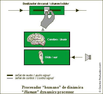
The concept of a dynamics processor is really
not that different from that of a person changing the volume by moving a mixer
fader. For instance, if we have a singer that starts singing too loud or getting
too close to the microphone, we will reduce the volume on that voice's channel.
In that case we are proving compression. When the singer is not singing, we may
move the fader all the way down to avoid background noise leaking into the main
outputs, thereby acting as a noise gate. There is basically a process whereby someone
is listening to the volume changes of a signal and taking the decision of whether
the volume needs to be changed or not. The graph below illustrates the
process : the auditory system detects the volume changes, and the brain commands
the hand to bring the fader up or down as a function of the signal volume.

This human dynamics processor has its
limitations. It can only control one channel, it is slow, and its actions are
not repeatable. We might want to use a robot with an articulated arm that would
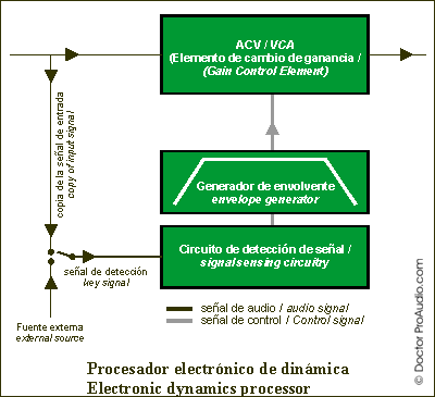
ride a mixer's faders. In practice, though, we choose an electronic device that
performs an equivalent function. The electronic version is not very different
from a philosophic point of view, though it does away with its limitations.
As show below, the input to a dynamics
processor is split into two. One of these signal copies will be processed by a
gain changing element, which will typically be a voltage controlled amplifier (VCA)
or a digital equivalent. The other copy goes to a detection circuit that rides
the VCA. For the volume changes to be smooth, an envelope generator is used to
ramp volume changes and thus avoid abrupt audible changes. The slope and shape
of the ramp can be modified, as we will see later. Often we can choose to feed
the detector with the input signal or, alternatively, an external signal which
is referred to as the "Side Chain" or "Key" signal.

One of the side effects of using analog
volume control elements (VCAs) to process the signal is noise. The quietest VCAs
tend to be expensive, and therefore only included in highly professional
equipment. As well as a good VCA, a quality dynamics processor also needs a good
detection stage, which is by no means easy to design. Which would explain why
only a handful of brands on both side of the Atlantic enjoy a reputation for
quality dynamics processors and are used for serious sound reinforcement. A
good dynamics processor should make it easy to control dynamics transparently,
avoiding any kind of audible undesired "pumping" and "breathing"
effects. Newer digital units, often built into digital mixers, do not suffer
from noise problems, though quality dynamics processing algorithms are not easy
to come by, and therefore it will probably be unrealistic to expect quality
compression or gating from inexpensive digital products.
1.3. Types
The more commonly used dynamics processors are :
A limiter is only a form of compressor.
There also exists the "true
expander", though in practice there are no commercial devices that perform
true expansion, which would entail amplifying signals above a specified level
and attenuating those below it, therefore expanding the dynamics of a
signal.
We could also speak of digital (those
that process a digitized signal) and analog devices. In reality, (good)
digital devices can work like their analog counterparts, though normally one
uses their processing power to increase manipulation possibilities. For
instance, for recording and other non-real time applications, we could compress a
signal using a "look-ahead" buffer to make compression/limiting decisions
based on what is still to come, so that, for instance, we could start
compressing a peak before it exceeds the threshold, avoiding the transient
overshoot that would occur on an analog compressor and doing so in an inaudible
way.
1.4. Controls
Different dynamics processors will provide differing sets of controls and
indicators. In general, the controls we will find on dedicated units (built-in
ones may obviate some of the controls) are :
- Threshold. When the signal goes above or below this level, the processing starts.
- Attack time. It's the time it takes for the signal to get attenuated/limited/muted/amplified. In general, low attack times work better with low frequency signal and, conversely, faster attack times do a better job with high frequency signals. When processing a full range signal, attack times are generally based on the lowest frequencies present in the signal.
- Release time. It's the opposite of attack time, i.e., the time it takes for the signal to go from a processed state to not being processed. Release times are normally longer than attack times.
- Hold Time. Specifies the minimum time that a compressor or gate will process the signal for.
- Ratio. Defines the amount of attenuation or gain that will be applied to the signal. On noise gates, it may be pre-set so that it is just a muting effect.
- Stereo Link. Used to process a stereo signal such that both channels are always processed at the same time, even if one of them has not triggered the processing. This avoids confusing image shifts from the center to one of the sides when only one of the channels is being compressed or gated.
- Automatic. It is becoming more and more common to control some of the parameters defined above (typically attack and release times) automatically based on the signal characteristics. This control activates or deactivates that feature.
- Bypass. Allows comparing of the original versus the processed signal.
1.5. Meters and indicators
The most common visual indicators provided on dynamics processors are given
below. You may not always find them, or you may get additional ones:
- Gain or attenuation meter. It is normally implemented as a row of LEDs and indicates the amount of attenuation or gain being applied, to visually judge whether we are over processing or not processing at all. On noise gates we will normally only find an activation light.
- Activation LED. Shows when processing is taking place.
- -Source ( doctorproaudio.com)